Small portable circuit board etcher.

After having had a several years long break from working with electronics I have finally got started again. I started with building very small projects build on experimental board. Quite soon though, I wanted to make proper circuit boards. It is not really a big job to make your own circuit boards. It just requires some good working space and the proper equipment. Living in a flat in the centre of Amsterdam, space is sparse. So I have been creating my circuits on the kitchen table. But mixing photo print developer and etchant with food production is not an ideal situation.
So to keep things a little more efficient and less space (and time) consuming I wanted to build a device that would do the etching without me having to stay constantly over the whole etching process. And more importantly; when finished etching it is easy to clean and store the etcher in the cupboard.
The Etcher
The etcher has been build entirely from materials I had lying around. Well almost - I bought the power plug so I could avoid having to sling around with a fixed wire. This also makes the etcher easy to store in the cupboard when finished etching.
From another project I had a few pieces of 4mm MDF over. Looking through the kitchen cupboards I found a transparent dishwasher proof food container with lid. The stepper motor and the cog are from an old HP Ink-Jet printer. I never got to use the motor because of its quite low step resolution. Fortunately the stepper motor is quite strong, taking its size in to consideration. The only special component is the stepper driver IC. I had a couple of the driver ICs in my component drawer from some experiments I had been doing some time ago. The rest of the components are all standard components.
 |
| The stepper motor has a resolution of 48steps/revolution. |
The etcher will tilt the etchant container slowly up and down with the help of an eccentric wheel attached via a cog to the stepper motor. The eccentric wheel is, like the box, made from 4mm MDF. It was meant for testing purpose only, but turned out to work quite well. I polished the rim with fine sand paper and gave it a couple of layers of floor varnish to make the surface both extra smooth and hard. The eccentric wheel only needs to lift a couple of hundred grams so the wear and tear is quite limited.
With my initial build I mounted the eccentric wheel directly to the cog on the stepper motor. This made the whole etcher vibrate quite a lot and made it very noisy. I tried to run the stepper motor in half step mode and that reduced the noise to a quite actable level. After doing a few etches though I decided that the noise was too much anyway. So I mounted an extra cog between the stepper motor and the eccentric wheel. That also meant that I could increase the speed of the stepper motor and thereby reducing the vibrations and make it nearly silent.
 |
| The initial eccentric wheel mounted directly on the stepper motor. This caused the whole etcher to vibrate and be quite noisy. |
 |
| Using a cog between the stepper and the eccentric wheel allowed me to increase the speed of the stepper and thereby reducing the noise to a minimum. |
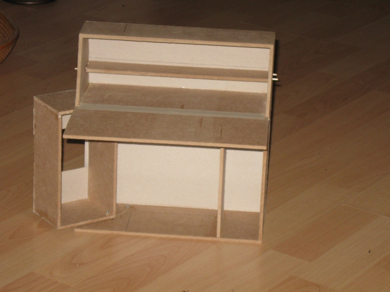
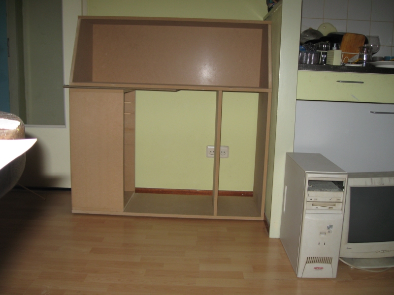
The etcher box is build from 4mm MDF I had lying around. I glued the pieces together with good wood glue. I attached a piece of piano hinge to the back and lid of the etcher to allow both the tilting of the etchant container and to give access to the circuit board.
 |
| Under the hood. |
The Circuit
The circuit diagram below contains stepper motor driver with speed control, the temperature control and power supply.
 |
| Circuit Diagram |
Stepper Driver
The stepper motor I have used is actually a 6 wire bi-polar motor but I use it here as a 4 wire uni-polar motor. The reason for that was basically that I had a driver for that configuration lying in the drawer.
The stepper motor driver is build around an H-Bridge driver IC - MC3479. The stepper motor has a quite low step resolution (48 step/rev.) and it is rather noisy if run at a low speed.
The clock input of the stepper motor driver is created by a simple oscillator build around the well known CD4093. This is a quadruple 2 input NAND gate with smith trigger input.
The speed can be adjusted so that the etchant slowly waves over the circuit board to be etched.
Heat Control
I am using natriumpersulphat for etching. This etchant works best at a temperature between 45°C and 50°C. To heat the etchant to the optimal etching temperature, some kind of heating element was needed.
My initial idea was to use some length of constantan wire for the heating element. But that gave me a couple of challenges to overcome. Firstly; my local electronics store only sells constantan wire in big roles with several hundred meters of wire and costing nearly €60. I would only need a few meters so I thought it was a little over the top. Secondly; I would have to build some kind of mechanical frame to hold the constantan wire.
Another idea was to use some power resistors. That would be a cheap solution, but again the mechanical build would be bulky and unpractical. So after a few calculations and experiments with a circuit board I decided to try it out.
The heating element is simply made from a piece of 100 x 100 mm thin circuit board with one long single track. The total track length is around 5.5 m. The track width is 12mil (0.012”) that gives a resistance of the track just around 12 Ohm. The heating element is glued to the etchant container with heat resistant epoxy glue to give a good thermal connection.
 |
| The heating element glued to the bottom of the etchant container with heat resistant epoxy glue. |
The heating element is connected to the box with a short length of wire and a plug. This makes it possible to detach the etchant container for rinsing, cleaning and storage.
 |
View of the etcher with power cord, stepper motor and connection to the heater.
|
The whole unit is fed from a 2 x 9V 1.5Amp ring core transformer. Again; I had it lying around from another project that had been shelved. The transformer is therefore also slightly under dimensioned - but I didn’t want to go buy a new one - they are quite pricy. Because of the under dimensioned transformer the speed of the stepper is slightly slower when the heater is on because of the voltage drop.
The heater gets fed from the total 18V. The rest of the circuit and stepper motor is fed from one 9V winding only.
The temperature is controlled by a very simple circuit build around a second gate of the CD 4093 smith trigger. It uses a voltage divider consisting of a 15k NTC resistor and a 10k trimmer. The midpoint of the voltage divider is fed to the input of the smith trigger which drives a transistor that switches the relay off when the desired temperature is reached. This is a very simple solution but in my setup it works like a charm. It keeps the etchant temperature just around 47°C.
The NTC resistor is mounted under the etchant container and is spring loaded so it stays in good thermal contact with the heater. So I do not measure the temperature of the liquid but the temperature of the heater itself. I used a normal thermometer, while doing the adjusting, to measure the temperature of the liquid.
The etchant container sits on a piece of 5mm thick foam. Mainly to keep the noise to a down, but it also ensures a good thermal contact between the NTC resistor and the heating element. It also makes the container sit quite sturdy. In the initial build it had a tendency to glide around, like when a mobile vibrates on the table.

 The 'spring loaded' NTC resister from the top and bottom.
The heating element can heat 1dl of etchant from room temperature to 45° in about 15 minutes. If preheating the etchant, the heater only needs to keep the temperature to the desired temperature while etching.
I usually pour the etchant in the etcher and start it at the same time as I start to expose the circuit board in the UV light box. In the time it takes to expose the circuit board the etchant has reached its optimal temperature. It now only needs to be kept the right temperature by the heating element. I use a light box build around an 8W UV-A lamp hacked from an old face browner I bought years ago in my more vain days.
See this post. The developing of the photo print takes about 25 minutes with the mentioned lamp so that leaves plenty of time to raise the temperature of the etchant.
Etching a circuit board
Here you can see the progress of the etching process.
 |
| The circuit board immediately get a pinkish colour. |
 |
| The etching is in progress. |
 |
| Just a few minutes left. |
 |
| The finished circuit board. Normally I do not use hatch pattern, so this was kind of an experiment. |
Circuit Board
Below is the circuit board. You can download the corresponding Eagle files
here .