Friday 7 April 2023

3D Printed - Modular - Kitchen Utensils - System.


I got a little tired of the mess in one of my kitchen drawers, so I started 3D printing a modular "tool holder".
The tools are all designed in Open SCAD, so basically consists of cylinders, and cubes.
  
I started with the holder for my mixer tools, as they always got tangled up. As that turned out to be a success, I continued with the rest of the kitchen tools I use most. Notice the prominent spot for cork-screw.

On the latter photo you can see the dove-tail connection between each module. The spool holder includes a little knife to cut the thread. Costs for the hole system - less than 1 euro in materials and hours and hours of fun designing each module.

Maybe the most used tool was a little tricky because of the curves.


This is where it started. The most useful of them all


And the companion tool. A foil cutter and rubber cork.
I got the set as a goodbye present from the last company I worked for in Denmark all the way back in 1998. It's of course Danish Design.


    Most of the tool holders has been created from simple shapes as cylinders and cubes.
For the Garlic press I used an other method. I took a photo of the presser and imported it into Open-SCAD. Saved a lot of time to do it this way because of the odd shape.


    The spool holder was probably the most fun to make.
This mainly because I wanted to include a knife to cut the thread.
The knife is just a piece of steel from a can of some sort. Probably canned tomatoes.
To create the knife blade I just made a small cut with my wire cutters and bend it a little to allow the threat to enter between the two sharp edged.


This holder is currently a bit of a failure. The fit is bad and the whiskers won't stay put. Luckily it's just one module - I can replace it with a new better version, or maybe for an other tool.


These two holders I just made because I felt I wanted to. The both turned out much better than expected.


Thursday 16 February 2023

 From Idea through Theory to Reality

For quite some time I wanted to make a bathroom cabinet, but never really got around to do it. I could of course have taken the easy way out by going to IKEA and buy a flat-pack. Though I'm Scandinavian, I'm not really an IKEA kind of guy. It's all a little to square for my taste.

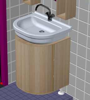
I finally got the finger out - So I fired up AutoCAD and started designing a bathroom cabinet that fitted my quirky taste. 

To be clear - I'm neither a designer, nor a vizard when it comes to creating 3D renderings, but I do enjoy the process of creating and building - and I have a lot of fun doing it. Isn't that the most important thing?


The cabinet as rendered in AutoCAD
And the reality.
Just needs a lick of paint so it can handle the bathroom environment.

Errors were made, struggles was fought, frustration ran high at curtain moments. Building the curved doors was probably the bigger challenge. 

I don't own a lot of woodworking tools and I do all the building work in my living room, so I decided to use GAMMA's woodcutting service for some of the wood. They did a brilliant job. The wood was cut precise and had a very nice finish.

To help me getting through the build I bought myself a new Jigsaw - that was a lifesaver as I needed quite a few curved pieces of wood - and GAMMA's service is still quite limited in what they can make.

The cabinet is build from 3 mm multiplex for the sides and doors. 9 mm multiplex for the bottom, shelf and top. The inner construction is made from 27 * 27 mm pinewood.

The idea was to bend the multiplex for the doors around some curved pieces of pinewood, but the 3 mm multiples was quite a bit more stiff than I had expected, so I had to give up on that. Fortunately I did have some 2 mm birch multiplex from an other old project and there was just enough for the doors. The did result in two different wood types (as can also be seen in the photo above) Also, because the birchwood was thinner (only by 1 mm) I did have to make some minor adjustments here and there.

because of the two different wood types, I'm probably going to paint the sides plain white and leave the doors with clear coating so you can see the birchwood finish.

The following is just a bunch of snap-shots taken during the build. 

The "skeleton" is done. That was the easy part.

The cutout for the sink took quite some measuring. I did 3D printed a helping tool to transfer the shape of the sink. That removed some of the guesswork and I could finally get to use my new Jigsaw.
 
The shelf was easy finished using the Jigsaw.


The framework for the first door is ready.

Starting to clue up the door, this was the easy part.

Continuing the glue up. I had to do this in small steps
as I didn't have enough clamps to do it in one go.

The first door is ready.

The second door went a little more smoothly than the first.
Mainly because I learnt from the mistaken made on the first.

Both doors are ready - and a still have all me fingers (and a few splinters)

View from the back. Nearly looks like a chair from the 1930's.
Maybe that could be my next project...

The, nearly finished, cabinet. It fits in the allocated spot with only a few millimeters to spare.
Next step. Going the whole lot with filler and sanding it down to prepare it for painting.


Sunday 15 January 2023

Upgrade Power Supply with Fan Cooling.


The finished upgraded power supply.

After a bunch of years - in the middle of a long running 3D print, my printer suddenly stopped. The bed fell to the ground, well the base of the printer, with a bang.

My first thought was - Oh crap. Now I need a new 3D printer and can't really afford it at the moment. After the initial panic went away, my second thought was - Maybe it is only the power supply, a little optimism newer hurts. So I measured the output voltage of the power supply and got nada.

So I went shopping for a replacement. The specifications of the old power supply was: 12V / 5.3A.

Although I normally go to Conrad.nl for that kind of shopping, I was not able to find any good replacement. The search functionality at Conrad.nl really sucks. So I went to Bol.com and found a 12V / 6A replacement. Well a little more power couldn't hurt, so I ordered the power supply.

The new power supply was delivered next very day and of course had to be tested, so I found a simple object to print.

To my big disappointment my 3D printer stopped again after about an hour of printing. Damn - Maybe it was not only the power supply that had failed after all. When picking up the power supply to check the connections, it was hot as Hell, so it had obviously over heated and shut down. 

It's of course good the the power supply have thermal shut down, but it should be able to run continuously at its max ratings.

I tried to let the power supply cool down and did another test print. This time it finished without issues, but the power supply was again way too hot. 

So though the specifications for the power supply was on the good side and the Bol.com site stated that the supply should be usable for 3D printers, the closed enclosure, without any air vents, caused it to over heat. Not very handy for a 3D printer supply that is supposed to be able to run continuously for several hours or sometimes even days . 

Because the power supply "only" gave up on long running prints, I decided to try to add some active cooling to the supply. 

Getting the case open was a little bit of an issue. I thought it was one of these thermo clued cases thar are impossible to open - so I went for my hack saw and gingerly started to hack the case open. Got in - and realised that the case was clipped together not glues. Well too late and I was in.

There were 3 very small cooling fins. One glued to the top of the output transformer. One on the input MOS-FET and the last one, the smallest, on the output rectifier diode.

It was the cooling fin on the output rectifier diode that got very hot.

Fortunately I had a small 12V fan in stock, so I could easily attach that to the sower supply. The fan I'm using is 40 * 40 * 10 mm and is very quiet. So I went ahead and installed the fan on the now somewhat molested original case. Some hot glue and masking tape made that an easy job. Not a looker, but enough for testing.
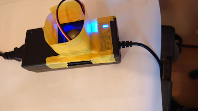
The somewhat molested power supply held together with hot glue and masking tape.

As the original case was now in a very poor condition I went ahead and designed a new case in OpenScad. The dimensions of the new case is only slightly larger than the original one, though a little taller. I placed the fan close to the overheating diode, and the air outlet as close to the coldest part of the power supply. That way, with some luck, all warm components would get some airflow.

Printing the case took a couple of hours. The power supply barely got hand warm now. So the little fan did its work. Quite a good result for such a small fan - and very sketchy set-up.


OpenScad model of the new power supply case.

Another view of the case.
Another OpenScad view of the case.

The new case is just a little larger than the old one.

The finished case looks good and works great. I had a few issues with the tolerances, but fixed that with a little bit of sanding. I regret I didn't install a power switch on the case, as I don't want the fan to run 24/7. Luckily I can print an upgrade in an hours time. So when I get a switch ordered I will fix that.
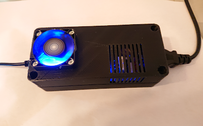

The finished upgraded power supply.